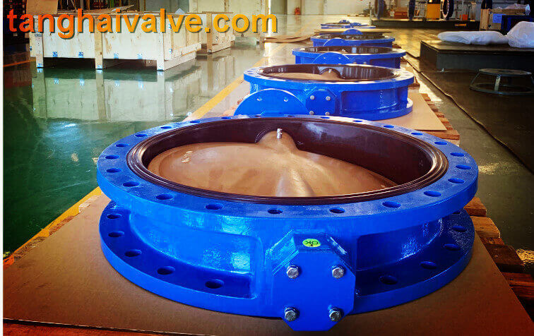
Tag Archive for: valve actuation

Posts

Corrosion Resistance of Marine Butterfly Valves

The corrosion resistance of marine butterfly valves is a critical factor in their selection and application, especially in marine environments. Due to the presence of salt spray, high humidity, and seawater’s corrosive nature, marine equipment requires superior corrosion-resistant properties. Below are key aspects related to the corrosion resistance of marine butterfly valves:

1. Material Selection

Material plays a crucial role in determining the corrosion resistance of marine butterfly valves. Common materials include:

  • Stainless Steel(e.g., 316, 316L): Offers excellent resistance to corrosion and is suitable for saltwater and corrosive chemical media.
  • Bronze: Resists saltwater corrosion and is commonly used in seawater piping systems.
  • Duplex Stainless Steel: Combines high strength with resistance to pitting and crevice corrosion, making it ideal for harsh marine environments.
  • Plastic Linings(e.g., PTFE, PVDF): Plastic-lined valves enhance corrosion resistance, making them suitable for handling highly corrosive media.

2. Coating and Protection

Marine butterfly valves often feature coatings or surface treatments to improve corrosion resistance:

  • Epoxy Coatings: Enhance resistance to corrosion, particularly in seawater contact areas.
  • Thermal Spray Coatings: Application of corrosion-resistant alloys (e.g., nickel-based alloys) provides additional protection.
  • Anodizing(for aluminum alloys): Improves surface hardness and resistance to oxidation.

3. Design Features

  • Seal Material Selection: Resistant materials such as EPDM or fluororubber are often used for seals to prevent failures due to corrosion.
  • Optimized Structure: Minimizing gaps and dead zones reduces the accumulation of corrosive substances.

4. Environmental Impact

  • In marine environments, salt spray and electrochemical corrosion require special attention to pitting and crevice corrosion resistance.
  • For valves submerged in seawater for extended periods, electrochemical corrosion prevention methods such as cathodic protection are essential.

5. Standards and Certifications

The materials and corrosion resistance of marine butterfly valves must comply with international or industry standards, such as:

  • ISO 15156(Standards for materials resistant to sulfide stress corrosion).
  • DNV GL, ABS, BV Certifications: International classification societies impose stringent requirements for corrosion protection in marine equipment.

6. Maintenance and Care

Regular inspection and cleaning of the valve surface, along with timely replenishment or replacement of coatings, can effectively extend the service life of marine butterfly valves.

In summary, the corrosion resistance of marine butterfly valves depends primarily on material selection, surface treatment technologies, and appropriate adaptation to specific environmental conditions. During design and selection, it is crucial to consider factors such as media properties, operating temperature, and pressure comprehensively.

Shaft Materials in Marine Valve

Shafts in marine valves are critical components that connect the actuator or handwheel to the valve’s internal components, allowing for control of fluid flow. The material selection for marine valve shafts depends on the application, operating environment, and fluid type. Common shaft materials in marine valve applications include:

1. Stainless Steels

  • Grade 316/316L:
    • High corrosion resistance, particularly against seawater and marine atmospheres.
    • Suitable for most marine applications, including those handling water, oils, and certain chemicals.
  • Duplex Stainless Steels (e.g., 2205):
    • High strength and superior corrosion resistance.
    • Excellent performance in environments with high chloride concentrations (e.g., seawater).
  • Super Duplex Stainless Steel (e.g., 2507):
    • For highly aggressive environments, including high-pressure seawater systems.

2. Bronze and Brass Alloys

  • Aluminum Bronze (e.g., C95400, C95800):
    • Excellent resistance to marine corrosion and biofouling.
    • Commonly used in seawater applications.
  • Nickel-Aluminum Bronze:
    • Provides higher strength and wear resistance.
    • Often used in valves for seawater and hydraulic systems.

3. Monel (Alloy 400)

  • High resistance to corrosion, particularly in saltwater and acidic conditions.
  • Ideal for highly corrosive environments, including marine chemical systems.

4. Hastelloy (e.g., C276, C22)

  • Exceptional resistance to chemical corrosion.
  • Used in marine environments with aggressive chemicals or extreme conditions.

5. Titanium

  • Excellent resistance to seawater corrosion and lightweight.
  • Used in specialized, high-performance applications (e.g., submarines, desalination systems).

6. Carbon Steel (with coatings)

  • Less expensive but requires protective coatings (e.g., epoxy, galvanizing) to prevent corrosion in marine environments.
  • Typically used in less demanding applications.

7. Nickel Alloys

  • Provides excellent resistance to oxidation and chloride-induced corrosion.
  • Often used in valves for extreme marine environments.

Material Selection Factors:

  • Corrosion Resistance: Seawater and chlorides are particularly aggressive.
  • Strength and Durability: High-pressure systems require stronger materials.
  • Temperature Resistance: Some applications involve elevated temperatures.
  • Chemical Compatibility: Fluids handled by the valve may demand specific material compatibility.
  • Cost: Balancing performance with budget constraints.

When designing or selecting shafts for marine valves, proper consideration of operating conditions and regulatory standards (e.g., ABS, DNV, or IMO) is crucial to ensure reliability and compliance.

Application of Concentric type Resilient Seated Butterfly Valve in Marine Vessel

Concentric type resilient seated butterfly valves are commonly used in marine vessels for several reasons:

Leakage Prevention: The resilient seat provides a tight seal, reducing the risk of leakage in critical applications. This is crucial in marine environments where leaks can lead to significant safety and operational issues.

Corrosion Resistance: These valves are often made from materials that resist corrosion, which is essential for marine applications due to the harsh saltwater environment.

Compact Design: The concentric design allows for a compact and lightweight valve, which is beneficial in the space-constrained environment of a marine vessel.

Ease of Operation: These valves generally have a simple design that makes them easy to operate, which is important for maintaining efficient and reliable operation on a vessel.

Flow Control: They provide effective flow control, which is necessary for managing various systems on a marine vessel, such as cooling systems, ballast systems, and fuel systems.

Maintenance: The design typically allows for easier maintenance and replacement, which is advantageous for keeping the vessel in good working condition.

The concentric type resilient seated butterfly valve is valued in marine applications for its reliability, resistance to corrosion, and ease of maintenance, all of which contribute to the safe and efficient operation of marine vessels.

Tianjin Tanghai Valve Co., Ltd. is a professional marine valve manufacturer, including butterfly valve, check valve, gate /Knife gate valve. We have certificates: CE, ISO, BV, DNV foundry and products approval. Now we have our own independent R & D, manufacturing, assembly and warehousing workshops; we have professional pre-sale and after-sale technical support and perfect services. Below is our wafer butterfly valve of marine valves,if you need to check more information, please click here:https://www.tanghaivalve.com/wafer-type-butterfly-valve-th-btv-aw/.

Please contact us if you need more support, please contact us freely: info@tanghaivalve.com.

We are committed to “Build a top valve enterprise; Be a reliable partner!”Friends from all over the world are welcome to visit us for evaluation, guidance, and orders!

Classification of valve

There are many types of valves, and they can be classified in various ways.

  1. Classification by automation and actuation

Automatic Valves: These valves operate automatically relying on the medium (liquid, gas, steam, etc.) itself. Examples include safety valves, check valves, pressure reducing valves, and automatic exhaust valves.

Actuated Valves: These valves are operated manually, electrically, hydraulically, or pneumatically. Examples include butterfly valves, gate valves, and ball valves.

II.Classification by purpose and function

Shut-off Valves: Primarily used to stop or start the flow of the medium. This includes gate valves, globe valves, plug valves, ball valves, butterfly valves, etc.

Regulating Valves: Primarily used to regulate the flow, pressure, etc., of the medium. This includes control valves, throttle valves, pressure reducing valves, etc.

Check Valves: Used to prevent the backflow of the medium. This includes various types of check valves.

Diverting Valves: Used to distribute, separate, or mix the medium. This includes various types of distribution valves, three-way valves, and steam traps.

Safety Valves: Used for overpressure safety protection, releasing excess medium to prevent pressure from exceeding the specified value. Examples include safety valves.

Multi-function Valves: Used to replace two, three, or more types of valves, such as globe check valves, check ball valves, etc.

Other Special Valves: Examples include drain valves, pigging valves, etc.

III. Classification by main parameters

1, Classification by nominal diameter The nominal diameter is a rounded integer value used as a convenient reference to indicate the valve size. It is an approximate value rather than an exact measurement. The nominal diameter is marked with the letters “DN” (nominal diameter) followed by a value in millimeters. For example, a valve with a nominal diameter of 50 millimeters is marked as DN50.

  • Small diameter valves: Valves with DN≤40mm
  • Medium diameter valves: Valves with DN50-DN300mm
  • Large diameter valves: Valves with DN350-DN1200mm (4) Extra-large diameter valves: Valves with DN≥1400mm

2, Classification by pressure Nominal pressure refers to the design-specified pressure related to the mechanical strength of the pipeline components. The pressure is marked with “PN” followed by a pressure value (MPa). For example, PN1.0 indicates a valve with a nominal pressure of 1.0 MPa. (1) Vacuum valves: Valves with a working pressure lower than standard atmospheric pressure. (2) Low-pressure valves: Valves with a nominal pressure of PN<1.6 MPa. (3) Medium-pressure valves: Valves with a nominal pressure of PN 2.5–6.4 MPa. (4) High-pressure valves: Valves with a nominal pressure of PN 10.0–80.0 MPa. (5) Ultra-high-pressure valves: Valves with a nominal pressure of PN≥100 MPa.

3, Classification by working temperature of the medium (1) High-temperature valves: Valves with t > 450℃ (2) Medium-temperature valves: Valves with 120℃ ≤ t < 450℃ (3) Normal-temperature valves: Valves with -40℃ ≤ t < 120℃ (4) Low-temperature valves: Valves with -100℃ ≤ t < -40℃ (5) Ultra-low-temperature valves: Valves with t < -100℃

4, Classification by valve body material (1) Non-metallic material valves: Such as ceramic valves, fiberglass valves, plastic valves (2) Metallic material valves: Such as copper alloy valves, Monel alloy valves, cast iron valves, carbon steel valves, alloy steel valves (3) Metal body lined valves: Such as lead-lined valves, plastic-lined valves, enamel-lined valves.

5, Classification by connection method to the pipeline (1) Flange connection valves: Valves with flanges on the body, connected to the pipeline using flanges. (2) Threaded connection valves: Valves with threads on the body, connected to the pipeline using threads. (3) Welded connection valves: Valves with weld ends on the body, connected to the pipeline using welding. (4) Clamp connection valves: Valves with clamps on the body, connected to the pipeline using clamps. (5) Ferrule connection valves: Valves connected to the pipeline using ferrules.

III. Common Classification This classification method is based on principle, function, and structure and is the most commonly used classification method domestically and internationally. It generally includes gate valves, globe valves, plug valves, ball valves, butterfly valves, diaphragm valves, check valves, throttle valves, safety valves, pressure reducing valves, steam traps, and control valves.

Tianjin Tanghai Valve Co., Ltd. is a professional marine valve manufacturer, including butterfly valve, check valve, gate /Knife gate valve. We have certificates: CE, ISO, BV, DNV foundry and products approval. Now we have our own independent R & D, manufacturing, assembly and warehousing workshops; we have professional pre-sale and after-sale technical support and perfect services. Below is our wafer butterfly valve of marine valves,if you need to check more information, please click here:   https://www.tanghaivalve.com/wafer-type-butterfly-valve-th-btv-aw/

Please contact us if you need more support, please contact us freely: info@tanghaivalve.com.We are committed to “Build a top valve enterprise; Be a reliable partner!”Friends from all over the world are welcome to visit us for evaluation, guidance, and orders!

The Application of Concentric type Butterfly Valve in Offshore Drilling Platforms

Concentric type butterfly valves find several applications in offshore drilling platforms due to their reliability, compact design, and ease of operation. Here’s how centerline butterfly valves are used in offshore drilling platforms:

  1. Flow Control in Seawater Systems:

Concentric butterfly valves are used to control the flow of seawater for different purposes:

Cooling Systems: Regulating seawater flow for cooling heat exchangers, engines, and other equipment.

Firewater Systems: Controlling seawater flow for firefighting purposes.

General Service Water: Regulating water flow for various platform operations.

  1. Fluid Control in Drilling Operations:

Drilling Mud Systems: Controlling the flow of drilling mud during drilling operations.

Mud Mixing Systems: Regulating the flow of chemicals and additives mixed with drilling mud.

  1. Ballast Systems:

Regulating the flow of seawater into and out of ballast tanks to adjust the platform’s stability and draft.

  1. Bilge and Drainage Systems:

Managing the discharge of bilge water and other drainage fluids from the platform to maintain a safe environment.

  1. Fire Protection Systems:

Concentric butterfly valves are used in firewater deluge systems and fire hydrant systems for emergency fire suppression.

  1. Potable Water Systems:

Regulating the flow of potable water for living quarters, kitchens, and other facilities on the platform.

  1. HVAC Systems:

Controlling the flow of seawater or chilled water for heating, ventilation, and air conditioning systems.

  1. Tank Farm Operations:

Handling the flow of various liquids such as crude oil, refined products, and chemicals within the platform’s storage tank systems.

Key Advantages in Offshore Applications:

Corrosion Resistance: Materials are selected to withstand corrosive marine environments.

Space Efficiency: Compact design is suitable for installations where space is limited, which is common in offshore platforms.

Quick Operation: Rapid opening and closing for emergency shutdown situations.

Reliable Sealing: Provides tight shut-off to prevent leaks, crucial for safety and environmental protection.

Safety and Emergency Shutdown Systems:

Concentric butterfly valves are often integrated into safety systems, including emergency shutdown (ESD) systems, to quickly isolate sections of piping in case of emergencies.

Concentric type butterfly valves play a vital role in offshore drilling platforms, ensuring efficient fluid control, safety, and environmental protection. Their versatility, reliability, and space-saving design make them well-suited for various critical applications in offshore oil and gas operations. Proper selection, installation, and maintenance of these valves are essential to ensure the safe and efficient operation of offshore drilling platforms.

Tianjin Tanghai Valve Co., Ltd. is a professional marine valve manufacturer, including butterfly valve, check valve, gate /Knife gate valve. We have certificates: CE, ISO, BV, DNV foundry and products approval. Now we have our own independent R & D, manufacturing, assembly and warehousing workshops; we have professional pre-sale and after-sale technical support and perfect services. Below is our wafer butterfly valve of marine valves,if you need to check more information, please click here:https://www.tanghaivalve.com/wafer-type-butterfly-valve-th-btv-aw/.

Please contact us if you need more support, please contact us freely: info@tanghaivalve.com.We are committed to “Build a top valve enterprise; Be a reliable partner!”Friends from all over the world are welcome to visit us for evaluation, guidance, and orders!

What is the positive transmission of gears

When the total displacement coefficient of a pair of gears is greater than 0, it is a positive transmission.
Positive transmission refers to the positive displacement design of the gear. If two gears meshing with each other are in positive displacement, their center distance is greater than (the pair of gears) standard center distance. Conversely, if both gears use negative displacement, the center distance is smaller than the standard center distance. To judge whether the position is shifted, it is mainly to compare the measured gear parameters (including center distance) with the standard parameters of the gear to draw a conclusion.
Gear transmission is the most widely used transmission form in mechanical transmission. It has relatively

accurate transmission, high efficiency, compact structure, reliable work and long life. At present, the achievable indexes of gear technology: peripheral speed v=300m/s, rotation speed n=105r/min, transmitted power P=105KW, modulus m=0.004~100mm, diameter d=1mm~152.3mm
Features
1, the instantaneous transmission ratio is constant. The instantaneous transmission ratio of non-circular gear transmission can be designed according to the required change law.
2, the transmission ratio range is large, which can be used to decelerate or increase speed.
3, the range of speed (pitch circle speed) and transmission power is wide, and it can be used for high-speed (v>40m/s), medium-speed and low-speed (v<25m/s) transmission; power is from less than 1W to 105KW.
4, high transmission efficiency. A pair of high-precision involute cylindrical gears has an efficiency of over 99%.
5, compact structure, suitable for short-distance transmission.
6, the manufacturing cost is higher. Certain gears with special tooth shapes or high precision require special or high-precision machine tools, cutting tools and measuring instruments, so the manufacturing process is complicated and the cost is high.
7, low-precision gears, noise, vibration and shock during transmission, pollute the environment.
8, no overload protection
According to the relative position of the two shafts and the direction of the gear teeth, it can be divided into the following types:
<1>Straight tooth cylindrical gear drive;
<2> Helical cylindrical gear drive
<3> herringbone gear transmission;
<4> bevel gear transmission;

bevel gear

bevel gear

<5> cross-axis helical gear transmission.
According to the working conditions of the gear, it can be divided into:
<1>; Open gear transmission type gear transmission, the gears are exposed, and good lubrication cannot be guaranteed.
<2>; half-open gear transmission, the gear is immersed in the oil pool, with a protective cover, but not closed.
<3>; closed gear transmission, gears, shafts and bearings are all installed in a closed box, with good lubrication conditions, difficult for dust and sand to enter, accurate installation,
Gear transmission has good working conditions and is the most widely used gear transmission.
Gear transmission can be classified according to the relative position of its axis.
Gear drive can be divided into cylindrical gear drive, bevel gear drive, non-circular gear drive, rack drive and worm drive according to the shape of the gear.
According to the tooth profile curve, it can be divided into involute gear transmission, cycloid gear transmission and arc gear transmission. A transmission composed of more than two gears is called a gear train. The gear transmission can be divided into ordinary gear transmission and planetary gear transmission according to whether there are gears with axis movement in the gear train. The gears with axis movement in the gear train are called planetary gears. Gear transmission can be divided into closed type according to its working conditions
Gear transmission calculation
Open and semi-open transmission. Sealing the transmission in a rigid case and ensuring good lubrication is called closed transmission, which is more commonly used, especially for higher-speed gear transmissions, which must be closed transmission. Open transmission is exposed and cannot guarantee good lubrication. It is only used for low speed or unimportant transmission. Half-open transmission is somewhere in between.
The law of meshing:  The smoothness of gear transmission requires the instantaneous transmission ratio in the process of gear tooth meshing i=angular speed of driving wheel/angular speed of driven wheel=ω1/ω2=constant, this requirement is guaranteed by tooth profile. Figure 2 shows that the two meshing tooth profiles E1 and E2 are in contact at any point K, and the common normal line N1N2 of the two tooth profiles is made through the point K, which intersects the connecting center line O1O2 at point C. The condition for maintaining contact during the meshing process of the two tooth profiles is that the velocity of the K point on the tooth profile E1, vK1, and the K point velocity on the tooth profile E2, vK2, are equal in the direction of the common normal line N1N2, that is, vKn1=vKn2=vKn. Make perpendicular lines from O1 and O2 to the N1N2 line and intersect at points N1 and N2. The above formula shows that the two-wheel tooth profile must meet the following conditions: “No matter where the two-wheel tooth profile is in contact at any position, the common normal line passing through the contact point must pass the fixed point C ─ ─ node on the connecting center line.” This is a circular gear. The basic law of tooth profile meshing. There are many curves that can meet this law. In fact, the requirements of manufacturing, installation and load-bearing capacity should be considered. Generally, only involute, cycloid and arc are used as the working tooth profile of the gear. Part of the tooth profile is involute.
For involute gears, the base radius rb1 and rb2 of wheel 1 and wheel 2 are respectively. The N1N2 line is the internal common tangent of the two base circles, that is, the common normal of any contact point of the two tooth profiles coincides with it. Because the two base circles have only one internal common tangent in one direction, the common normal of any contact point passes through the fixed point C, which shows that using an involute as the tooth profile conforms to the basic law of tooth profile meshing.
The two circles drawn through node C with O1 and O2 as the centers are called pitch circles. The pitch radius of wheel 1 and the pitch radius of wheel 2 Involute gears have the following characteristics: ①N1N2 is the trajectory of the contact points of the two tooth profiles, called the meshing line, which is a straight line. ②The common tangent line tt of the two pitch circles of gear transmission through node C is called the meshing angle α’between it and the meshing line N1N2, which is a constant. ③The pressure between the tooth surfaces is always along the direction of the common normal line N1N2 of the contact point, so the pressure direction between the tooth surfaces does not change when the involute gear transmits power. ④The transmission ratio is inversely proportional to the radius of the base circle of the two wheels. After the gear is made, the base circle is determined. Therefore, even if the center distance is slightly deviated from the design during operation, the transmission ratio will not be affected. This feature is called the separability of the transmission. It affects the processing, assembly and Maintenance is very beneficial. ⑤The two tooth profiles only have no sliding between the tooth surfaces when the node C is in contact, and there is sliding between the tooth surfaces when they are in contact at other points, and the farther away from the node, the greater the sliding. ⑥Since the involute gear can mesh with a rack with a linear tooth profile, it can be processed by a tool with a linear tooth profile. The tool is easy to manufacture and the machining accuracy can be high.
Coincidence degree: Coincidence degree is an important parameter that affects the continuous transmission of gears. As shown in Figure 2, gear tooth meshing starts from the contact between the tooth root of the driving wheel and the tooth tip of the driven wheel, that is, the intersection A of the tooth tip circle of the driven wheel and the meshing line is the starting point of meshing. As the wheel 1 rotates, the wheel 2 is pushed to rotate, and the contact point moves along the meshing line. When the contact point moves to the intersection E of the addendum circle of the wheel 1 and the meshing line (the dotted line in the figure), the tooth profile When the meshing ends, the two tooth profiles begin to separate. Point E is the meshing end point, which is the actual meshing line length. If the front pair of teeth are still in contact at point D before point E, and the latter pair of teeth are in contact at point A, then the transmission is continuous; if the front pair of teeth has left at point E, and the latter pair has not yet entered meshing , Then the transmission is interrupted. Considering the influence of gear manufacturing, installation errors and deformation, ε≥1.1~1.4 is often required in practice. The greater the coincidence degree, the more stable the transmission. The above refers to the coincidence degree of the end face of the cylindrical gear, and there is a longitudinal coincidence degree for the helical cylindrical gear.
The condition for a pair of gears to be able to mesh correctly is that they must have equal modulus and equal pressure angle.

TH Valve is a professional manufacturer of butterfly valvegate valvecheck valveglobe valveknife gate valve, ball valve with API, JIS, DIN standard, used in Oil, Gas, Marine industry, Water supply and drainage, fire fighting, shipbuilding, water treatment and other systems, with Nominal Diameter of DN50 to DN1200, NBR/EPDM/VITON, Certificates & Approvals: DNV-GL, Lloyds, DNV, BV, API, ABS, CCS. Standards: EN 593, API609, API6D

Related news /knowledge:
what is Spur gear?
Types of mechanical transmission;
Common failures of butterfly valves and the characteristics of installation
Stainless steel valve material parameters and specific applications

What is the transmission ratio

In a mechanical transmission system, the ratio of the angular velocity or rotational speed of the driving wheel at the beginning and the driven wheel at the end.
Transmission ratio (i) = ratio of driving wheel speed (n1) to driven wheel speed (n2) = inverse ratio of gear index circle diameter = ratio of driven gear teeth (Z2) to driving gear teeth (Z1).
That is: i=n1/n2=D2/D1 i=n1/n2=z2/z1
For multi-stage gear transmission
1: The transmission ratio between every two shafts is calculated according to the above formula
2: The total transmission ratio from the first axis to the nth axis is calculated according to the following formula: Total transmission ratio ι=(Z2/Z1)×(Z4/Z3)×(Z6/Z5)……=(n1/n2)× (N3/n4)×(n5/n6)……

For multi-stage gear transmission

For multi-stage gear transmission

Extended information

The ratio of the angular velocities of the two rotating components in the mechanism is also called the speed ratio. The transmission ratio of component a and component b is Ⅰ=ωa/ωb=na/nb, where ωa and ωb are the angular velocities (radians/sec) of components a and b, respectively; na and nb are the rotational speeds of components a and b respectively ( Rpm) (Note: a and b after ω and n are subscripts).
When the angular velocity in the formula is an instantaneous value, the obtained transmission ratio is the instantaneous transmission ratio. When the angular velocity in the formula is an average value, the obtained transmission ratio is the average transmission ratio. For most gear transmissions and friction wheel transmissions with the correct tooth profile, the instantaneous transmission ratio is unchanged; for chain transmission and non-circular gear transmission, the instantaneous transmission ratio is variable.
For meshing transmission, the transmission ratio can be expressed by the number of teeth Za and Zb of wheel a and wheel b, i=Zb/Za; for friction transmission, the transmission ratio can be expressed by the radius Ra and Rb of wheel a and wheel b, i=Rb/Ra, At this time, the transmission ratio generally means the average transmission ratio.
In hydraulic transmission, the transmission ratio of the hydraulic transmission element generally refers to the ratio of the turbine speed S and the pump wheel speed B, that is, =S/B. Hydraulic transmission elements can also be combined with mechanical transmission elements (generally with various gear trains) to obtain various transmission ratios of different values ​​(see gear trains for gear train transmission ratios).

Types of mechanical transmission

There are many forms of mechanical transmission, which can be divided mainly into two categories:
1. Friction transmission that transmits power and motion by friction between parts, including belt transmission, rope transmission and friction wheel transmission. Friction transmission is easy to achieve stepless speed change, and it can mostly adapt to transmission occasions with large shaft spacing. Overload and slip can also play a role in buffering and protecting the transmission device. However, this type of transmission is generally not used in high-power applications and cannot guarantee accuracy. The transmission ratio.
2. The meshing transmission of power or movement by the meshing of the driving part and the driven part or the meshing of intermediate parts, including gear transmission, chain transmission, spiral transmission and harmonic transmission. The meshing transmission can be used in high-power applications with accurate transmission ratio, but generally requires higher manufacturing accuracy and installation accuracy.

According to the forms of force transmission, mechanical transmission can be divided into:

1 Friction drive.
2 Chain drive.
3 Gear drive.
4 Belt drive.
5 Turbo worm drive.
6 Ratchet drive.
7 Crankshaft connecting rod drive
8 Pneumatic transmission.
9 Hydraulic drive (hydraulic planer)
10 Universal joint drive
11 Wire rope drive (most widely used in elevators)
12 coupling drive
13 Spline transmission.
1. Features of belt drive
Including driving wheel, driven wheel and endless belt.
1) It is used in the situation where the two axes are parallel and the rotation direction is the same, which is called the concept of opening motion, center distance and wrap angle.
2) The belt type can be divided into three categories: flat belt, V belt and special belt according to the cross-sectional shape.
3) The focus of application is: calculation of transmission ratio, stress analysis and calculation of belt, and allowable power of a single V belt.
Advantages-suitable for transmission with a large center distance between two axles; the belt has good flexibility, can alleviate impact and absorb vibration; slip when overloaded to prevent damage to other parts; simple structure and low cost.
Because the belt is elastic and is driven by friction, it has a simple structure, stable transmission, low noise, and can buffer and absorb vibration. When overloaded, the belt will slip on the pulley and protect other parts from overload. It is suitable for center distance Advantages such as larger transmission.
But belt transmission also has many shortcomings. The main ones are: accurate transmission ratio cannot be guaranteed, transmission efficiency is low (approximately 0.90~0.94), belt service life is short, and it is not suitable for use in high temperature, flammable, oil and water situations.
2. Gear transmission
Classification: plane gear transmission, space gear transmission.
Features
Advantages-Wide range of applicable peripheral speed and power; accurate, stable, and high-efficiency transmission ratio; high reliability and long life; transmission between parallel shafts, intersecting shafts at any angle and intersecting shafts at any angle can be realized.
Disadvantages-requires higher manufacturing and installation accuracy, higher cost; not suitable for long-distance transmission between two shafts.
The names of the basic dimensions of involute standard gears include addendum circle, tooth root circle, index circle, touch number, pressure angle, etc.
1. The range of power and speed transmitted by the gear is very large, the power can be as small as hundreds of thousands of kilowatts, and the peripheral speed can be as small as more than one hundred meters per second. The gear size can range from less than 1mm to more than 10m.
2. Gear transmission belongs to meshing transmission, the gear tooth profile is a specific curve, the instantaneous transmission ratio is constant, and the transmission is stable and reliable.
3. High gear transmission efficiency and long service life.
4. There are many kinds of gears, which can meet the needs of various transmission forms.
5. The manufacturing and installation of gears require high precision.
4. Features of chain drive
1) To ensure a more accurate transmission ratio (compared with belt transmission)
2) Power can be transmitted when the center distance between the two shafts is far (compared to gear transmission)
3) Can only be used for transmission between parallel shafts
4) After the chain wears out, the chain links become longer, which is easy to cause chain disconnection.
5. Worm gear drive
It is suitable for movement and dynamics between two axes that are vertical and not intersecting in space.
Features
Advantages-large transmission ratio. ; Compact structure size.
Disadvantages-large axial force, easy to heat, low efficiency; only one-way transmission.
The main parameters of the worm gear drive are: modulus, pressure angle, worm gear index circle, worm index circle, lead, number of worm gear teeth, number of worm heads, transmission ratio, etc.
Single-stage transmission can obtain a large transmission ratio, compact structure, smooth transmission, no noise, but low transmission efficiency. Two-stage transmission solves the shortcomings of single-stage transmission.
6. The characteristics of spiral transmission: high transmission accuracy, stable operation, no noise, easy to self-lock, and can transmit greater power.

In the valve industry, there are many ways to open and close the valve plate. we call it valve drive method. as below:

Unit two, valve drive mode (code name):

drive mode Electro-magne-tism Electro-magnetic hydraulic Electro-hydraulic tur-bine Spur gear Bevel gear pneu-matic Hydr-aulic Gas-hydr-aulic elec-tric han-dle Hand-wheel
code 0 1 2 3 4 5 6 7 8 9

See the link for more details: https://www.tanghaivalve.com/valve-model-establishment-and-meaning/

TH Valve is a professional manufacturer of butterfly valvegate valvecheck valveglobe valveknife gate valve, ball valve with API, JIS, DIN standard, used in Oil, Gas, Marine industry, Water supply and drainage, fire fighting, shipbuilding, water treatment and other systems, with Nominal Diameter of DN50 to DN1200, NBR/EPDM/VITON, Certificates & Approvals: DNV-GL, Lloyds, DNV, BV, API, ABS, CCS. Standards: EN 593, API609, API6D

Related news/knowledge:
What is the transmission ratio
What is the positive transmission of gears
Form and types of Gear transmission
Stainless steel valve material parameters and specific applications

Form and types of Gear transmission

Gear transmission types:

As per the mutual position of the two wheel axes, gear transmission can be divided into plane gear transmission and space gear transmission.
According to the type of gear transmission:

BS5163-BB-NRS-soft seated-wedge gate valve-DN700-PN16-bevel gear (8)

BS5163-BB-NRS-soft seated-wedge gate valve-DN700-PN16-bevel gear (8)

1. According to the relative position of the two shafts and the direction of the gear teeth, it can be divided into the following types:
<1>Cylinder gear drive;
<2>Bevel gear transmission;
<3> Cross-axis helical gear transmission.
2. According to the working conditions of the gear, it can be divided into:
<1> Open gear transmission, the gears are exposed, and good lubrication cannot be guaranteed;
<2>Half-open gear transmission, the gear is immersed in the oil pool, with a protective cover, but not closed;
<3> Closed gear transmission, gears, shafts and bearings are all installed in a closed box, with good lubrication conditions, difficult to enter dust, accurate installation, gear transmission with good working conditions, and it is the most widely used gear transmission.
3. According to the hardness of the tooth surface:
<1>Soft tooth surface gear The hardness of the tooth working surface is less than or equal to 350HBS or 38HRC;
<2>Hard tooth surface gear The hardness of the tooth working surface is greater than 350HBS or 38HRC. When a pair of gears are driven.

The form of gear transmission:
1. Parallel shaft gear (cylindrical gear)
(1) Spur gear: A straight cylindrical gear with tooth ribs parallel to the axis.
(2) Rack (Rack): A linear gear that meshes with a spur gear. It can be said to be a special situation when the pitch of the gear becomes infinite.
(3) Internal gear: The inner gear of a straight cylinder that meshes with the spur gear.
(4) Helical gear: Cylindrical gears with helicoid teeth.
(5) Helical rack: a linear gear that meshes with a helical gear.
(6) Double helical gear: a helical gear formed by left and right spiral tooth ribs.

2. Right-angle shaft gear (bevel gear)
(1) Straight bevel gear: A bevel gear whose tooth ribs are consistent with the generatrix (straight line) of the pitch cone.
(2) Spiral bevel gear: A bevel gear with a bevel line with a spiral angle.
(3) Zero helical bevel gear (Zerol bevel gear): a bevel gear with zero helix angle.

3. Gears with staggered shafts (worm gear and worm)
(1) Cylindrical worm gear: Cylindrical worm gear is the general name of worm (Worm) and gear (Wheel).
(2) Staggered helical gear (screw gear): This is a cylindrical helical gear, which is called when it is used for transmission between staggered shafts (also known as skew shafts).
(3) Other special gears: Face gear: a disc-shaped face gear that can mesh with a spur gear or a helical gear. Concave worm gear: Concave worm gear and its meshing gear. Hypoid gear: Conical gear that conveys the wrong axis. The shape is similar to a curved bevel gear.

TH Valve is a professional manufacturer of butterfly valvegate valvecheck valveglobe valveknife gate valve, ball valve with API, JIS, DIN standard, used in Oil, Gas, Marine industry, Water supply and drainage, fire fighting, shipbuilding, water treatment and other systems, with Nominal Diameter of DN50 to DN1200, NBR/EPDM/VITON, Certificates & Approvals: DNV-GL, Lloyds, DNV, BV, API, ABS, CCS. Standards: EN 593, API609, API6D

Related news/knowledge:
What is the positive transmission of gears
Types of mechanical transmission
Stainless steel valve material parameters and specific applications

Comparison of pneumatic actuator, electric actuator and hydraulic actuator

The valve actuators used in the regulating valve are nothing more than pneumatic, electric and hydraulic:

hydraulic actuator for marine valve

hydraulic actuator for marine valve

1. Nowadays, most of the actuators used in industrial control places are because they use air source as power, which is more economical than electric and hydraulic, and has a simple structure, which is easy to control and maintain. From a maintenance point of view, it is easier to operate and proofread than other types of actuators, and it is also easy to realize the call of positive and negative on the spot. Its biggest advantage is safety. When using a locator, it is ideal for flammable and explosive environments. If the electrical signal is not explosion-proof or intrinsically safe, there is a potential risk of fire caused by ignition. Therefore, although the application range of electric control valves is becoming wider and wider, in the chemical industry, pneumatic control valves still occupy an absolute advantage.

2. Electric actuators: Electric actuators are mainly used in power plants or nuclear power plants, because the high-pressure water system requires a smooth, stable and slow process. The main advantages of electric actuators are high stability and constant thrust applied by users. The maximum thrust generated by the actuator can be as high as 225000kgf. Only hydraulic actuators can achieve such a large thrust, but the cost of hydraulic actuators is higher than that of electric Much higher. The anti-deviation ability of the electric actuator is very good, and the output thrust moment is basically constant, which can well overcome the unbalanced force of the medium and achieve accurate control of the process parameters, so the control accuracy is higher than that of the pneumatic actuator . If equipped with a servo amplifier, the positive and negative effects can be exchanged easily, and the signal-off valve position state (hold/full open/full close) can be easily set, and it must remain in the original position when it fails. What the pneumatic actuator cannot do, the pneumatic actuator must rely on a set of combined protection system to achieve position retention.

Hydraulic actuator: When we need abnormal anti-deflection ability, high thrust and fast formation speed, we often choose hydraulic or electro-hydraulic actuator. Because of the incompressibility of hydraulics, the advantage of using hydraulic actuators is better anti-deviation ability, which is very important for regulating conditions, because when the regulating element is close to the valve seat, the throttle condition is unstable. The larger the pressure difference, the worse this situation is. In addition, the hydraulic actuator runs very smoothly and responds quickly, so high-precision control can be achieved. The electro-hydraulic actuator integrates the motor, the oil pump, and the electro-hydraulic servo valve. It can work as long as it is connected to the power supply and the control signal. The hydraulic actuator is similar to the cylinder, but it can withstand higher pressure than the cylinder. Work requires an external hydraulic system. The factory needs to be equipped with hydraulic stations and oil pipelines. In contrast, electro-hydraulic actuators are more convenient.