Tag Archive for: resistance butt welding

Posts

What is butt welding? (8)- typical workpieces

Butt welding of typical workpieces
1, butt welding of small section workpieces

wire with diameter d≤5mm is mostly used for resistance butt welding,
Small diameter wires, wires of different materials, and wires and stamping parts (such as resistors and diode end caps) can be welded by capacitive energy storage type, which is characterized by very hard welding conditions and
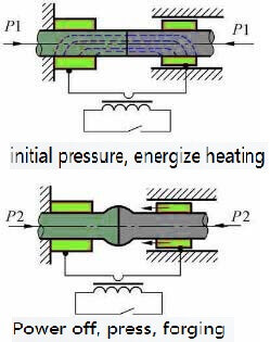
resistance butt welding-Schematic diagram

resistance butt welding-Schematic diagram

extremely narrow heating range, which greatly reduces The influence of the thermal and physical properties of the welded metal on the formation of the joint.
2. Butt welding of rods
is mostly used in the butt welding of steel bars in the construction industry, usually resistance butt welding is used for diameter d<10mm; continuous flash butt welding for d>10mm; preheated flash butt welding for d>30mm. When using a manual butt welding machine, because the power of the welding machine is small (usually not more than 50KVA), when d=15-20mm, it is generally necessary to use preheated flash butt welding.

Semi-circular or V-shaped clamp electrodes can be used for butt welding of rods. The latter can be used in various diameters, so it is widely used. The rods are of solid cross-section, with greater rigidity, and longer extension lengths can be used.
3, pipe butt welding
Pipe butt welding is widely used in boiler manufacturing, pipeline engineering and petroleum equipment manufacturing. Choose continuous or preheated flash butt welding according to the section and material of the pipe. The clamp electrode can be semicircular or V-shaped. Usually when the ratio of pipe diameter to wall thickness is greater than 10, a semicircle can be selected to prevent the pipe from being crushed. V-shape can be used when the ratio is less than 10. To prevent the tube from slipping in the clamp electrode, the clamp electrode should have an appropriate working length. When the pipe diameter is 20-50mm, the length of the workpiece is 2-2.5 times the pipe diameter; when the pipe diameter is 200-300mm, it is 1-1.5 times.

Because the tube has an expanded cross-section, the heat dissipation is faster, the liquid metal on the end surface is easy to cool, and it is difficult to extrude during upsetting. The area is scattered, and the self-protection effect is weakened during the flashing process. Therefore, when the process parameters are not selected properly, non-metallic inclusions will remain in the interface to form gray spot defects. Maintain stable flash, increase flash and upsetting speed, and adopt gas protection to reduce or eliminate gray spots.

After the pipe is welded, the internal and external burrs need to be removed to ensure that the external surface of the pipe is smooth and there is a certain channel aperture inside. Deburring requires special tools.

4, thin plate butt welding
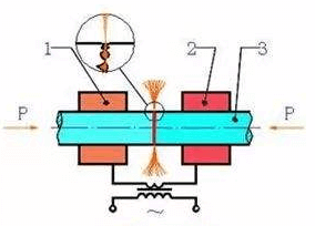
flash butt welding-schematic diagram

flash butt welding-schematic diagram

Thin plate butt welding is widely used in the continuous production line of rolled steel plate in the metallurgical industry. The width of the plate is from 300 to 1500mm or more, and the thickness is from less than 1mm to more than ten mm. The materials include carbon steel, alloy steel and non-ferrous metals and their alloys. After the plate is butt welded, the joint will undergo rolling and produce great plastic deformation, so it must not only have a certain strength, but also a high plasticity. For steel plates with a thickness of less than 5mm, continuous flash butt welding is generally used, and a plane electrode is used for single-sided conduction. When the plate is thick, preheated flash butt welding is used for double-sided conduction to ensure uniform heating along the entire end surface.

When welding thin plates, due to the relatively large cross-section length and width, the area is scattered, the joint cools quickly, and the self-protection effect is weak during the flashing process. At the same time, the liquid lintel is small and the liquid metal layer on the end surface is thin. Prone to oxidation and solidification. Therefore, the flashing and upsetting speed must be increased. After welding, the burr must be removed with a burr cutting device while it is hot.
5. Butt welding of ring parts
When welding ring parts (such as wheel rims, chain rings, bearing rings, jet engine mounting edges, etc.), in addition to considering the general rules of butt welding process, attention should be paid to the influence of shunting and ring deformation elasticity. Due to the shunt, the required power should be increased by 15-50%. Although the diameter of the ring decreases, the cross section increases, and the material resistivity decreases.

When the ring parts are butt welded, the upsetting pressure must consider the influence of the deformation rebound force, but because the shunt has the effect of heating the ring back, the increase in the upsetting pressure is not large.

Bicycles, motorcycle rims, and automobile rims all use continuous flash butt welding, and the front mouth of the clamp electrode must match the cross-section of the workpiece. During upsetting, in order to prevent the rebound force from affecting the quality of the joint, or even pull the joint apart, it is necessary to extend the time of no current upsetting.

Chain links such as anchor chains and drive chains are mostly used in the manufacture of low-carbon steel and low-alloy steel. Resistance butt welding can be used when diameter d<20mm, and preheating flash butt welding can be used when d>20mm. The purpose of preheating is to heat the interface. Uniform, easy to produce certain plastic deformation during upsetting.
6, tool butt welding
When cutting tool butt welding, one of the current process methods used to manufacture blanks in tool manufacturing is mainly the butt welding of high-speed steel (W8Cr4V, W-9Cr4V2) and medium carbon steel. Tool butt welding has the following characteristics:

1) The thermal conductivity and resistivity of high-speed steel and medium-carbon steel are quite different. At room temperature, medium carbon steel λ=0.42W/(cm℃), ρ0=18-22uΩcm; high-speed steel λ=0.23W/(cm℃), ρ0=48Ωcm. In order to make the temperature distribution on both sides of the joint surface basically the same , The extension length of high speed steel should be 30-50% smaller than that of medium carbon steel. Under normal circumstances, the extension length of high-speed steel is (0.5-1.0)d. In order to prevent excessive heat dissipation, the extension length is not less than 10mm.

2) High-speed steel has a high tendency to quench, the hardness after welding will be greatly increased, and quenching cracks may occur. In order to prevent cracks, preheating flash butt welding can be used. During preheating, heat the metal in the range of 5-10mm near the interface to 1100-1200℃. After welding, it is annealed in an electric furnace at 600-700℃ for 30 minutes.

3) When high-speed steel is heated to a high temperature, it will produce grain growth or the formation of ledeburite eutectic on the semi-melted grain boundary, making the joint brittle. The ledeburite eutectic cannot be eliminated by heat treatment. Therefore, it is necessary to use sufficient upsetting to eliminate this structure.

TH Valve is a professional manufacturer of butterfly valvegate valvecheck valveglobe valveknife gate valve, ball valve with API, JIS, DIN standard, used in Oil, Gas, Marine industry, Water supply and drainage, fire fighting, shipbuilding, water treatment and other systems, with Nominal Diameter of DN50 to DN1200, NBR/EPDM/VITON, Certificates & Approvals: DNV-GL, Lloyds, DNV, BV, API, ABS, CCS. Standards: EN 593, API609, API6D

Related news/knowledge:
What is butt welding? (1);
What is butt welding? (7)- Flash butt welding of common metals;
What is butt welding? (9)- New technology of flash butt welding;
What is butt welding? (5)- flash butt welding

What is butt welding? (2)

2. Welding cycle, process parameters and workpiece preparation for resistance butt welding

1, welding cycle

During resistance butt welding, the two workpieces are always pressed tightly. When the end face temperature rises to the welding temperature Tω, the distance between the end faces of the two workpieces is as small as a few

resistance butt welding-Schematic diagram

resistance butt welding-Schematic diagram

angstroms. The atoms between the end faces interact to produce common crystal grains on the joint. Form joints. There are two welding cycles in resistance butt welding: equal pressure and increased forging pressure. The former is simple and easy to implement. The latter is conducive to improving the quality of welding, and is mainly used for

resistance butt welding of alloy steel, non-ferrous metals and their alloys. In order to obtain sufficient plastic deformation and further improve the quality of the joint, a current upsetting procedure should be set.

2, process parameters

The main process parameters of resistance butt welding are: extension length, welding current (or welding current density), welding energization time, welding pressure and upsetting pressure.

(1) Overhang length l0 is the length of the workpiece over the end face of the clamp electrode. When selecting the extension length, two factors should be considered: the stability of the workpiece during upsetting and the heat dissipation to the clamp. If l0 is too long, the workpiece will lose stability during upsetting. If l0 is too short, due to the enhanced heat dissipation to the jaws, the workpiece will be cooled too strongly, which will increase the difficulty of plastic deformation. For the workpiece with diameter d, generally low carbon steel: l0=(0.5-1)d, aluminum and brass: l0=(1-2)d, copper: l0=(1.5-2.5)d.

(2) Welding current Iω and welding time tω In resistance butt welding, the welding current is often expressed by the current density jω. jω and tω are the two main parameters that determine the heating of the workpiece. The two can be adjusted accordingly within a certain range. High current density and short time (strong condition) can be used, or low current density and long time (weak condition) can be used. But when the condition is too strong, it is easy to produce incomplete penetration defects; when it is too soft, it will cause serious oxidation of the interface end surface, coarse grains in the joint area, and affect the strength of the joint.

(3) The welding pressure Fω and the upsetting pressure Fu, Fω have an effect on the heat generation and plastic deformation of the joint. Reducing Fω is good for heat generation, but not good for plastic deformation. Therefore, it is easy to use a smaller Fω for heating and a much larger Fu for upsetting. However, Fω should not be too low, otherwise it will cause splashing, increase end surface oxidation, and cause looseness near the interface.

3. Workpiece preparation

In resistance butt welding, the shape and size of the end faces of the two workpieces should be the same to ensure that the heating and plastic deformation of the workpieces are consistent. The end surface of the workpiece and the surface in contact with the clamp must be strictly cleaned. Oxide and dirt on the end face will directly affect the quality of the joint. The oxides and dirt on the surface of the workpiece in contact with the clamp will increase the resistance of the contact, which will cause the surface of the workpiece to burn, increase the wear of the jaws, and increase the power loss.

The workpiece can be cleaned by mechanical means such as grinding wheels, wire brushes, etc., or pickling.

Oxide inclusions easily occur in resistance welding joints. For rare metals, certain alloy steels and non-ferrous metals with high welding quality requirements, protective atmospheres such as argon and helium are often used to solve the problem.

Although resistance butt welding has the advantages of smooth joints, small burrs, and simple welding process, the mechanical properties of the joints are low, and the preparation of the end face of the workpiece is high, so it is only used for butt joints of small section (less than 250mm2) metal profiles.

What is butt welding? (1)

Butt resistance welding (hereinafter referred to as butt welding) is a type of resistance welding method that uses resistance heat to weld two workpieces along the entire end surface at the same time. Butt welding has high

welding

welding

productivity and easy automation, so it is widely used.
Application of butt welding:
Butt welding has high productivity and easy automation, so it is widely used. Its application range can be summarized as follows:
(1) The length of the work piece, such as the butt welding of strip steel, profile, wire, steel bar, rail, boiler steel pipe, oil and natural gas transportation pipeline.
(2) Butt welding of annular workpieces, such as car rims and bicycles, motorcycle rims, butt welding of various chain links, etc.
(3) Assembling welding of components The simple rolling, forging, stamping or machining parts are butt-welded into complex parts to reduce costs. For example, butt welding of automobile steering shaft shell and rear axle housing, butt welding of various connecting rods and tie rods, and butt welding of special parts.
(4) Butt welding of dissimilar metals can save precious metals and improve product performance. For example, the butt welding of the working part of the tool (high-speed steel) and the tail (medium carbon steel), the butt welding of the head (heat-resistant steel) and the tail (structural steel) of the exhaust valve of an internal combustion engine, the butt welding of aluminum and copper conductive joints, etc. .
Classification of butt welding:
Butt welding is divided into resistance butt welding and flash butt welding.
Resistance butt welding
Resistance butt welding is a method in which the end faces of the two workpieces are always pressed tightly, heated to a plastic state by resistance heat, and then upset pressure is quickly applied (or no upset pressure is applied and only the pressure during welding is maintained) to complete the welding.
One, resistance and heating of resistance butt welding
The resistance distribution during butt welding is shown in the figure. The total resistance can be expressed by the following formula:
R=2Rω+RC+2Reω
where Rω-the internal resistance of the conductive part of a workpiece (Ω);
Rc–the contact resistance between two workpieces (Ω);
Rω–The contact resistance between the workpiece and the electrode (Ω);
The contact resistance between the workpiece and the electrode is usually ignored due to its small resistance and far from the joint surface.
The internal resistance of the workpiece is proportional to the resistivity ρ of the welded metal and the length l0 of the workpiece extending from the electrode, and inversely proportional to the cross-sectional area s of the workpiece.
Same as spot welding, the contact resistance of resistance butt welding depends on the surface condition, temperature and pressure of the contact surface. When the contact resistance has obvious oxides or other stolen goods, the contact resistance is large. The increase in temperature or pressure will reduce the contact resistance due to the increase in the actual contact area. At the beginning of welding, the current density at the contact point is very large; after the end surface temperature rises rapidly, the contact resistance decreases sharply. When heated to a certain temperature (steel 600 degrees, aluminum alloy 350 degrees), the contact resistance disappears completely.
Like spot welding, the heat source during butt welding is also the resistance heat generated by the resistance of the welding zone. In resistance butt welding, the contact resistance exists for a very short time, and the heat generated is less than 10-15% of the total heat. But because this part of the heat is generated in a very narrow area near the contact surface. Therefore, the temperature in this area will increase rapidly, and the internal resistance will increase rapidly. Even if the contact resistance disappears completely, the heat generation intensity in this area is still higher than other places.
The harder the welding rod used (that is, the larger the current and the shorter the energization time), the smaller the pressing force of the workpiece, and the more obvious the influence of contact resistance on heating.