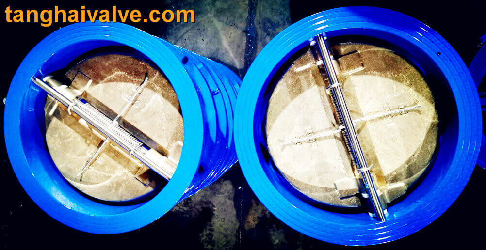
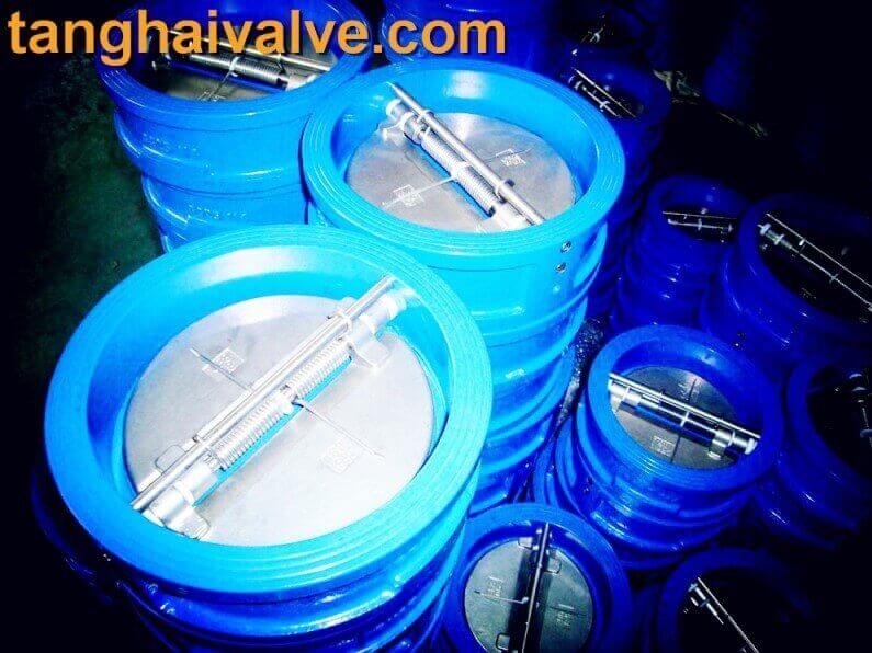
Disc Materials of Butterfly Check Valve(dual plate check valve)
The disc of a butterfly check valve plays a crucial role in controlling the flow of fluids by pivoting on a central axis to either open or close the valve. Depending on the application, pressure, and the fluid being handled, different materials are used for manufacturing the disc. Below are common materials used for butterfly check valve discs:
1. Stainless Steel
- Grades: 304, 316, 316L
- Characteristics: High resistance to corrosion, good mechanical properties, and durability. Suitable for water, steam, chemical, and food-grade applications.
- Common Uses: Petrochemical, food and beverage, and water treatment industries.
2. Carbon Steel
- Characteristics: Strong and cost-effective, but less corrosion-resistant than stainless steel. Usually requires coatings for corrosion protection.
- Common Uses: General-purpose industrial applications where corrosion resistance is not a primary concern.
3. Ductile Iron
- Characteristics: Combines strength and flexibility, offering good toughness and ductility. Requires coating (e.g., epoxy) for corrosion resistance.
- Common Uses: Water distribution, wastewater, and low-pressure applications.
4. Aluminum Bronze
- Characteristics: High corrosion resistance, particularly in seawater and marine environments. Good strength and wear resistance.
- Common Uses: Marine, seawater handling, and desalination plants.
5. Nylon-Coated Disc
- Characteristics: Nylon coating provides enhanced wear resistance and some degree of corrosion protection. Suitable for mildly corrosive environments.
- Common Uses: Low-pressure industrial applications.
6. Elastomer-Lined Disc (Rubber)
- Materials: EPDM, NBR (Nitrile), FKM (Viton)
- Characteristics: The disc is typically coated with elastomeric materials to provide a bubble-tight seal and resist specific chemicals. Different elastomers offer various resistances to temperature, chemicals, and abrasives.
- Common Uses: Applications requiring chemical resistance or sanitary conditions, like food processing and chemical plants.
7. Hastelloy
- Characteristics: Highly resistant to corrosive and harsh chemical environments, particularly acids and oxidizing agents.
- Common Uses: Chemical processing, pharmaceuticals, and industries dealing with corrosive fluids.
8. Monel
- Characteristics: Extremely resistant to corrosion, particularly from acids, alkalis, and seawater. Excellent mechanical strength.
- Common Uses: Marine, oil & gas, chemical, and heat exchanger applications.
9. Titanium
- Characteristics: Exceptional resistance to corrosion in seawater, chlorides, and acidic environments. Lightweight and highly durable.
- Common Uses: Aerospace, marine, chemical, and desalination applications.
The selection of disc material in a butterfly check valve is based on factors like the type of fluid being handled, the operating temperature and pressure, and the desired longevity of the valve.
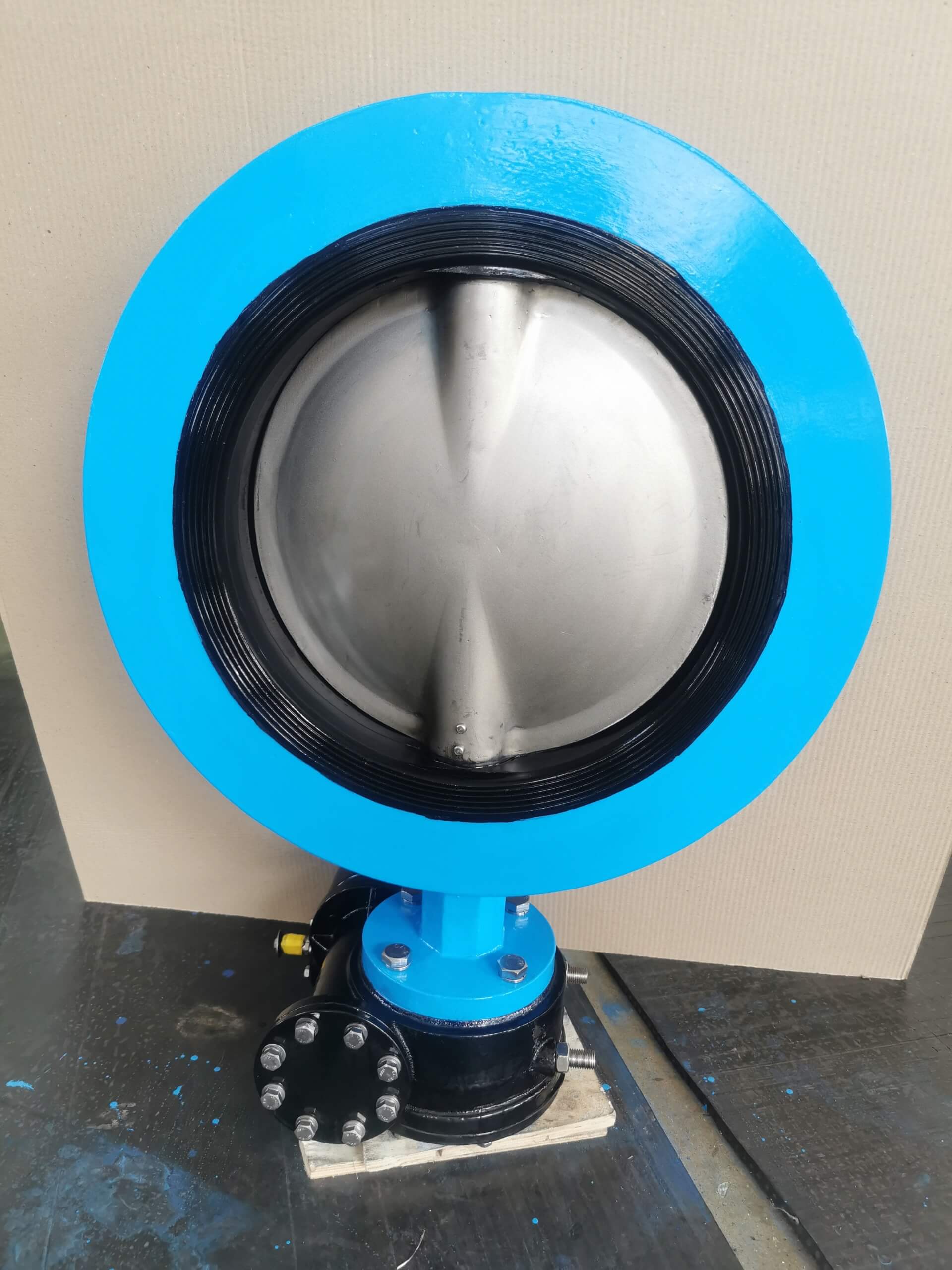
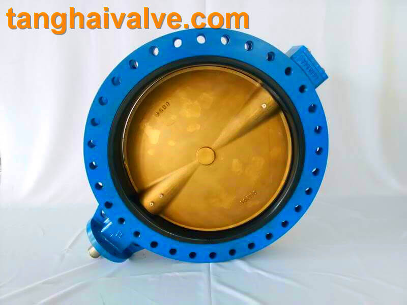
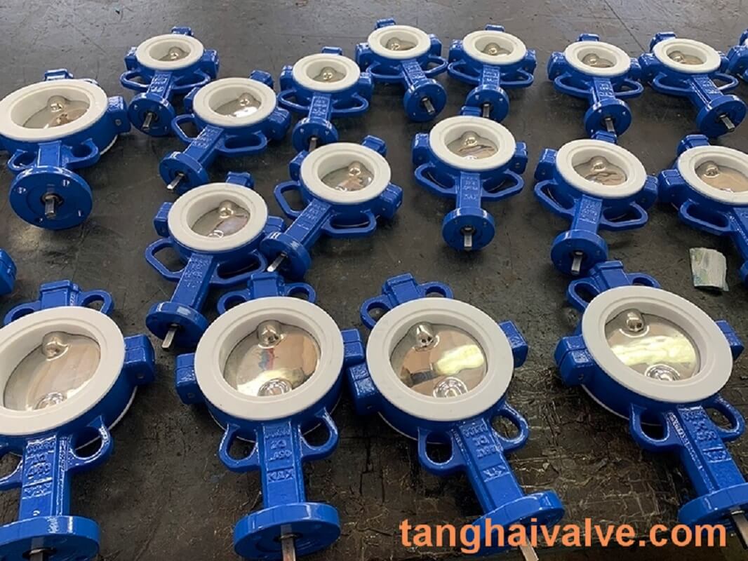
Tianjin Tanghai Valve Co., Ltd. is a professional marine valve manufacturer, including butterfly valve, check valve, gate /Knife gate valve. We have certificates: CE, ISO, BV, DNV foundry and products approval. Now we have our own independent R & D, manufacturing, assembly and warehousing workshops; we have professional pre-sale and after-sale technical support and perfect services. Below is our wafer butterfly valve of marine valves,if you need to check more information, please click here: https://www.tanghaivalve.com/wafer-type-butterfly-valve-th-btv-aw/
Please contact us if you need more support, please contact us freely: info@tanghaivalve.com.We are committed to “Build a top valve enterprise; Be a reliable partner!”Friends from all over the world are welcome to visit us for evaluation, guidance, and orders!