Valve actuator / actuation -(3)-classifications
Double acting valve actuator:
The selection of double-acting actuators takes DA series pneumatic actuators as an example. The output torque of
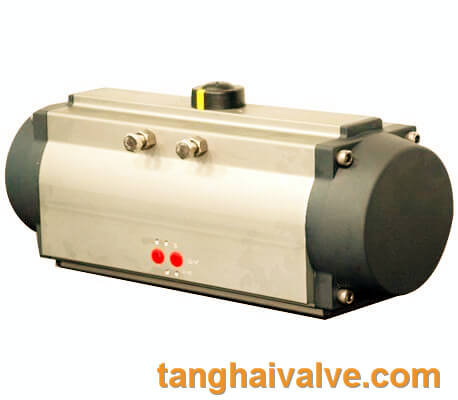
Pneumatic actuator (2)
the gear-and-pinion actuator is the piston pressure (supplied by the air source pressure) multiplied by the pitch circle radius (arm). And the friction resistance is small and the efficiency is high. The output torque is linear when rotating clockwise and counterclockwise. Under normal operating conditions, the recommended safety factor for double-acting actuators is 25-50%
Single-acting valve actuator:
The selection of single-acting actuator takes the SR series pneumatic actuator as an example. In the application of spring return, the output torque is obtained during two different operations. According to the stroke position, each operation produces two different torque values. The output torque of the spring-return actuator is obtained by multiplying the force (air pressure or spring force) by the force arm. The first situation: the output torque is obtained by air pressure entering the central cavity to compress the spring, which is called “air stroke output torque”. In this case, the air source pressure forces the piston to turn from 0 degrees to 90 degrees. Due to the reaction force generated by the compression of the spring, the torque gradually decreases from the maximum value
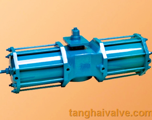
hydraulic actuator for marine valve
at the starting point to the second condition: the output torque is the spring recovery when the middle cavity loses air. The force acting on the piston is called “spring stroke output torque”. In this case, due to the extension of the spring, the output torque gradually decreases from 90 degrees to 0 degrees. As mentioned above, the single-acting actuator is based on two It is designed on the basis of generating a balance torque under this condition.
Linear valve actuator:
1. Through single seat valve
The so-called single seat means that there is only one valve core and one valve seat in the valve body. Its characteristics are simple structure, small leakage (even completely cut off) and small allowable pressure difference. Therefore, it is suitable for occasions requiring clean media with small leakage and small working pressure difference. Special attention should be paid to the allowable pressure difference in the application to prevent the valve from closing.
2. Straight through double seat valve
There are two valve cores and valve seats in the valve body of the straight-through double-seat regulating valve. Compared with the single seat valve of the same caliber, its flow capacity is about 20% to 25% larger. Because the force of the fluid on the upper and lower valve cores can cancel each other, but the upper and lower valve cores are not easy to close at the same time, the double seat valve has the characteristics of large allowable pressure difference and large leakage. Therefore, it is suitable for clean media where the pressure difference between the two ends of the valve is large and the leakage requirement is not high. It is not suitable for high viscosity and fiber-containing occasions.
3. Angle valve
The valve body of the angle control valve is right-angled, its flow path is simple, and the service force is small. It is suitable for the control of high pressure difference, high viscosity, suspended solids and granular materials. Generally used for bottom inlet and side outlet, this kind of control valve has better stability. In high pressure situations, in order to prolong the service life of the spool, the side inlet and the bottom outlet can be used, but oscillation is prone to occur in small openings.

