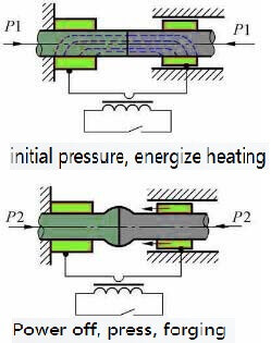
What is butt welding? (5)- flash butt welding
(4) Flash speed vf A sufficiently large flash speed can ensure the strong and stable flash. However, if vf is too large, the heating zone will be too narrow, which will increase the difficulty of plastic deformation. At the same time, due to the increase in welding current required, it will increase the depth of the fire hole after the lintel blasting, which will reduce the joint quality. The following factors should also be considered when choosing vf:
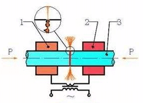
flash butt welding-schematic diagram
1) The composition and performance of the material being welded. For materials with a lot of easily oxidizable elements or good electrical and thermal conductivity, vf should be larger. For example, it is larger when welding austenitic stainless steel and aluminum alloy than when welding low carbon steel;
2) Whether there is preheating. When there is preheating, it is easy to excite the flash, so vf can be improved.
3) There should be a strong flash before upsetting. vf should be large to ensure a uniform metal layer on the end face.
(5) Upsetting flow rate δu δu affects the removal of liquid metal and the magnitude of plastic deformation. If δu is too small, liquid metal will remain in the interface, which will easily form defects such as looseness, shrinkage, cracks, etc.; when δu is too large, the crystal lines will bend severely and reduce the impact toughness of the joint. δu is selected according to the cross-sectional area of the workpiece and increases with the increase of the cross-sectional area.
During upsetting, in order to prevent the interface from oxidizing, the current should not be cut off immediately before the end face interface is closed. Therefore, the upsetting flow should include two parts-current upsetting allowance and non-current upsetting allowance. The former is the latter. 0.5-1 times.
(6) Upsetting speed vu In order to avoid the difficulty of liquid metal removal and plastic metal deformation due to metal cooling in the interface area, and to prevent the end surface metal from oxidizing, the faster the upsetting speed, the better. The minimum upsetting speed depends on the properties of the metal. The minimum upsetting speed for welding austenitic steel is twice that of welding pearlitic steel. The welding of metals with good thermal conductivity (such as aluminum alloy) requires a high upsetting speed (150-200mm/s). For the same metal, if the temperature gradient in the interface area is large, the upsetting speed needs to be increased due to the fast cooling rate of the joint.
(7) The upsetting pressure Fu Fu is usually expressed by the pressure per unit area, that is, the upsetting pressure. The size of the upsetting pressure should ensure that the liquid metal in the joint can be extruded and a certain degree of plastic deformation will be produced at the joint. If the upsetting pressure is too small, the deformation will be insufficient and the strength of the joint will decrease; if the upsetting pressure is too high, the deformation will be too large, the crystal lines will bend seriously, and the impact toughness of the joint will be reduced.
The size of the upsetting pressure depends on the metal properties, temperature distribution characteristics, upsetting allowance and speed, and the shape of the workpiece section. High-temperature and strong metals require large upsetting pressure. Increasing the temperature gradient will increase the upsetting pressure. Because the high flash speed will increase the temperature gradient, when welding metals with good thermal conductivity (copper, aluminum alloy), a large upsetting pressure (150-400Mpa) is required.
(8) Preheating flash butt welding parameters In addition to the above process parameters, preheating temperature and preheating time should also be considered.
The preheating temperature is selected according to the cross-section of the workpiece and the material properties. When welding low carbon steel, it generally does not exceed 700-900 degrees. As the cross-sectional area of the workpiece increases, the preheating temperature should be increased accordingly.
The preheating time is related to the power of the welding machine, the size of the workpiece section and the performance of the metal, and it can be changed in a relatively large range. The preheating time depends on the required preheating temperature.
In the preheating process, the amount of shortening caused by preheating is very small, and it is not specified as a process parameter.
(9) The clamping force Fc of the clamp must ensure that the workpiece does not slip during the upsetting. Fc is related to the upsetting pressure Fu and the friction coefficient f between the workpiece and the clamp. Their relationship is: Fc≥Fu/2f. Usually F0=(1.5-4.0) Fu, the lower limit is taken for low carbon steel with compact section, and the upper limit is taken for cold-rolled stainless steel plate. When the clamp is equipped with a top support device, the tightening force can be greatly reduced, and Fc=0.5Fu is sufficient at this time.
3. Workpiece preparation
The preparation of the workpiece for flash butt welding includes: the geometry of the end face, the processing of the blank end and the surface cleaning.
When flash butt welding, the geometry and size of the butt surface of the two workpieces should be basically the same. Otherwise, the heating and plastic deformation of the two workpieces will not be guaranteed to be consistent, which will affect the quality of the joint. In production, the difference in diameter of round workpieces should not exceed 15%, and the difference between square workpieces and tubular workpieces should not exceed 10%.
When flashing butt welding large-section workpieces, it is best to chamfer the end of a workpiece to increase the current density to facilitate the laser flash. In this way, the secondary voltage can be increased without preheating or initial flashing.
The butt welding blank end can be processed on a shear, punch, lathe, or plasma or gas flame cutting, and then the end face can be removed.
During flash butt welding, the end metal is burned out during flash, so the end face cleaning is not very strict. However, the cleaning requirements for the contact surface between the clamp and the workpiece should be the same as for resistance butt welding.