introduction of micro-resistance slow-closing butterfly check valve
Introduction of Micro-resistance Slow-closing Butterfly Check Valve
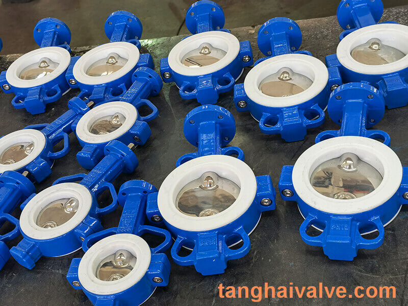
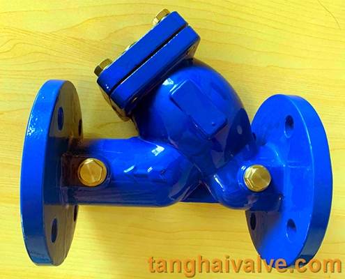
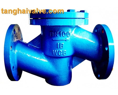
The structure of the butterfly check valve is very simple, and its structural length is also very short compared to other check valves. Butterfly check valve is also called butterfly check valve. The connection method is wafer type. The
micro resistance butterfly check valve (3)
valve plate is two semicircular butterfly plates. The two butterfly plates are connected by the valve stem and are forced to reset by spring. The working principle of the butterfly check valve is: when the medium flows through the valve body channel, the medium pressure is greater than the force of the spring, and the two discs are pushed open, the valve is opened, and the medium flows; when the medium stops flowing, the two discs Then due to the force of the spring, the valve is forced to reset, and the valve is closed, and the backflow of the medium is prevented at the same time.
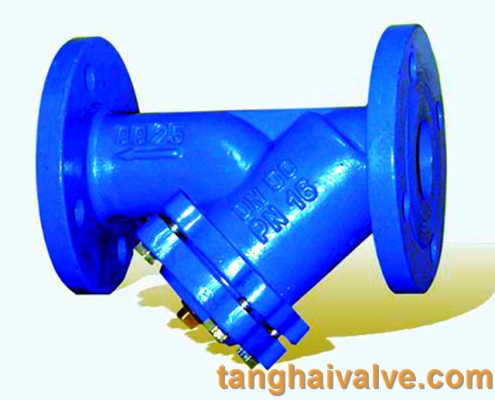
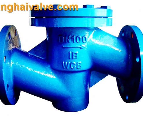
Butterfly check valve is also known as double-clip check valve. Its sealing surface can be surfacing wear-resistant material or lined with rubber. It has a wide range of use and reliable sealing. Butterfly check valves are automatic valves and do not require manual operation. This type of valve is usually used in pure pipelines, as well as pipelines in the fields of industry, environmental protection, water treatment, and high-rise building water supply and drainage, to prevent the backflow of the medium. To prevent the reverse flow of the medium.
The main code is HH46 HH48 HH49
Micro-resistance slow-closing butterfly check valve application
It is mainly used in the supply and drainage pipelines of purified water, source water, sewage, seawater and other media. It is installed at the outlet of the pump to cut off the backflow of the medium to eliminate destructive water hammer, protect the pipeline and make the pump run safely.
Features of Micro-resistance Slow-closing Butterfly Check Valve
micro resistance butterfly check valve (4)
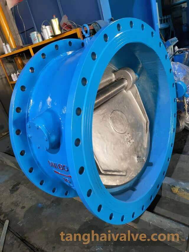
1. Small in size, light in weight, and only about one-third of the length of the swing check valve, it is more suitable for use in pipelines with limited space.
2. The slow closing system has excellent performance, long-term movement does not fail, can effectively control the slow closing of the valve disc, and can eliminate the destructive water hammer.
3. Rubber soft seal, good sealing performance, wear resistance, long service life and better stability. .
4. There is a closing spring on the valve disc, which opens and closes smoothly, without vibration and noise.
5. The flow channel is usually small in fluid resistance, sensitive in opening and closing of the valve plate, and good in sealing performance.
6. Compared with other check valves, the flow resistance is smaller, and it has obvious energy saving effect.
Micro-resistance slow-closing butterfly check valve main parts and materials
| Part Name | Material |
| valve body | Gray cast iron, carbon steel, ductile iron, stainless steel |
| Disc | Cast steel, ductile iron, stainless steel |
| stem, spring | Stainless steel |
| Slow closing device, micro-control valve | Stainless steel |
Main technical parameters of micro-resistance slow-closing butterfly check valve
| Nominal pressure (Mpa) | Shell test pressure (MPa) | Sealing test pressure (MPa) | proper temperature | Applicable media | Slow closing time |
| 1 | 1.5 | 1.1 | ≤80℃ | clean water, sewage, sea water | 3-60 seconds |
| 1.6 | 2.4 | 1.76 | |||
| 2.5 | 3.75 | 2.75 |
Product structure diagram of micro-resistance slow-closing butterfly check valve
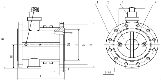
structure diagram of micro resistance butterfly check valve
The main connection dimensions of some products of the micro-resistance slow-closing butterfly check valve (unit: mm)
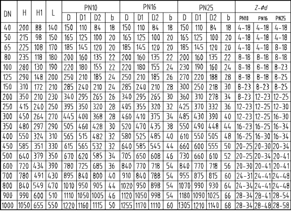
main dimensions-sizes of micro resistance butterfly check valve
Working principle of micro-resistance slow-closing butterfly check valve
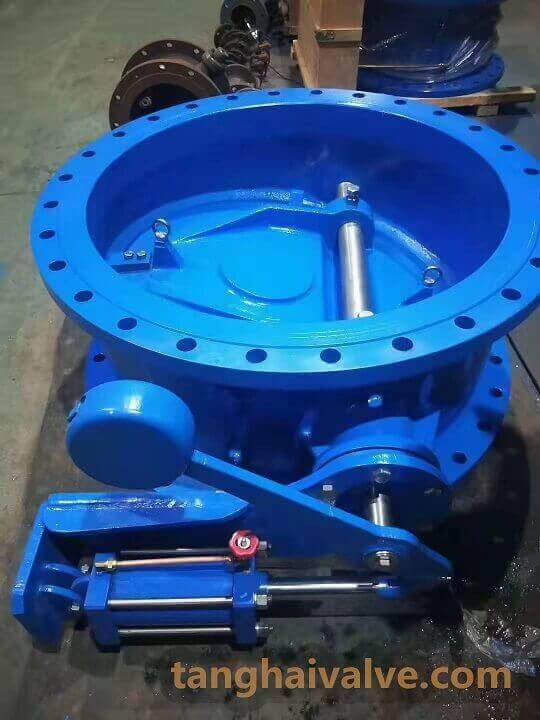
This check valve is mainly composed of a valve body, two semicircular discs, a return spring, an oil storage cylinder, a slow-closing small cylinder group, and a needle valve (micro-adjustment valve). Relying on the thrust of the imported medium, the two valve discs are pushed open smoothly. At the same time, the imported pressure medium enters the lower part of the piston in the oil cylinder, pushes the piston, and presses the oil on the upper part of the piston into the tail end of the small cylinder on both sides of the valve body through the needle valve, so that the piston rod in the small cylinder extends. When the inlet medium pressure drops below the outlet pressure, the medium will flow back, and the valve flap will automatically close under the action of the spring and the medium backflow. However, since the piston rod is in the extended position, it cannot be fully closed against the valve disc, and there is still about 20% of the area left for the medium to pass through, thus eliminating the water hammer. The valve disc is divided into two steps by the piston to quickly close first and then slowly to close, which can not only prevent the motor from reversing, but also play the role of eliminating mute.
Installation of Micro-resistance Slow-closing Butterfly Check Valve
1. The check valve can be installed horizontally (the arrow is parallel to the horizontal ground), or it can be installed vertically (the arrow is vertical to the horizontal ground).
2. Before installation, the pipeline should be cleaned, and the valve should be fully inspected to ensure that it is not damaged and then loaded into the pipeline. When loading, pay attention to the direction of the arrow and the running direction of the medium.
3. A filter should be installed at the inlet of the valve. A butterfly valve or gate valve should be installed at the outlet to facilitate the maintenance of the valve and other equipment.
4. When tightening the flange connecting bolts, attention should be paid to the symmetry, uniformity and firmness.
5. For a check valve with a working pressure greater than 1.0 MPa, the strength and tightness test should be carried out before installation, and it can be used only after passing the test. During the strength test, the test pressure is 1.5 times the nominal pressure, and the duration is not less than 5 minutes. The valve housing and packing should be qualified without leakage. During the tightness test, the test pressure is 1.1 times the nominal pressure; the duration of the test meets the requirements of GB 50243.
6. The check valve cannot bear the weight in the pipeline, and the large check valve should be supported independently so that it will not be affected by the pressure generated by the pipeline system.
Operation and debugging of micro-resistance slow-closing butterfly check valve
1. Initial test debugging
Close the needle valve on the oil reservoir clockwise, then open it counterclockwise for 3-5 turns.
2. Operation adjustment
After starting the water pump, observe whether there is oil leakage or water leakage at each connection of the slow-closing system. At the same time, use a wrench to loosen the screw plug on the needle valve body by one or two turns, so that the air in the slow-closing system can be discharged, and then quickly tighten the screw plug until there is leakage. When the pipeline pressure rises to a certain pressure, stop the pump and observe, there may be two situations at this time:
(1) The seal does not die when closed, and the motor reaches the speed of rotation faster. The reason for this phenomenon is that the opening of the needle valve is too small, and the pressure oil in the small cylinder does not return to the oil storage cylinder in a short time, so that the valve disc cannot be closed for a long time. At this point, just turn the needle valve counterclockwise half a turn to one turn.
(2) The seal is closed quickly, and the pipeline produces a great vibration sound. There are two reasons for this phenomenon: A) Because the opening of the needle valve is too large, the oil in the small cylinder quickly returns to the oil storage cylinder, that is, the valve disc is quickly closed to produce water hammer. At this time, try to close the small needle valve clockwise. If the small needle valve is closed and the pump is turned on for the second time, there is still a loud vibration when the pump is stopped again, which belongs to the reason B. B) The piston in the small cylinder does not extend. Check whether the needle valve is open, gently loosen the oil pipe joint at the small cylinder, and observe whether there is oil coming out. If there is oil leakage, it is proved that the oil circuit is unblocked. At this time, it may be because the oil in the oil storage is not enough, please refuel urgently. Refueling method: Disassemble the oil pipe joints on both sides of the needle valve, remove the needle valve counterclockwise with a wrench, insert a steel rod with a diameter of about 12mm and a length of about 300mm into the oil cylinder, and use a hammer to gently press the oil cylinder into the oil cylinder. The piston is knocked into the bottom end, at this time, add 20# oil to the oil cylinder, then install the needle valve, and then connect the copper pipe.
After the operation is adjusted, there is no need to move all parts, and it will work automatically and normally in the future.
TH Valve is a professional manufacturer of butterfly valve, gate valve, check valve, globe valve, knife gate valve, ball valve with API, JIS, DIN standard, used in Oil, Gas, Marine industry, Water supply and drainage, fire fighting, shipbuilding, water treatment and other systems, with Nominal Diameter of DN50 to DN1200, NBR/EPDM/VITON, Certificates & Approvals: DNV-GL, Lloyds, DNV, BV, API, ABS, CCS. Standards: EN 593, API609, API6D
Video of center-lined butterfly valve: https://youtu.be/NuSZH_AJcwY
Video of double eccentric butterfly valve: https://youtu.be/yOw2xp3bIaE
Video of triple eccentric butterfly valve: https://youtu.be/AkRwg2X1Wh0
Video of dual plate wafer check valve: https://youtu.be/XqRRI7o-LFI
Video of knife gate valve: https://youtu.be/vFSbTF_FGXM
Video of PTFE butterfly valve: https://youtu.be/Lutith_TJD0
Video of resilient seated gate valve: https://youtu.be/AI-LT1dy2sU
Related news/knowledge:
Ball check valve introduction
Slow-closing design of stainless steel swing check valve
Working Principle of Pneumatic Gate Valve
Pneumatic butterfly valve installation instructions