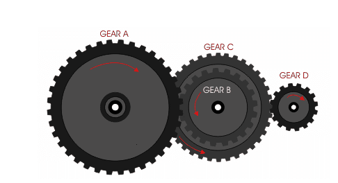
What is the positive transmission of gears
When the total displacement coefficient of a pair of gears is greater than 0, it is a positive transmission.
Positive transmission refers to the positive displacement design of the gear. If two gears meshing with each other are in positive displacement, their center distance is greater than (the pair of gears) standard center distance. Conversely, if both gears use negative displacement, the center distance is smaller than the standard center distance. To judge whether the position is shifted, it is mainly to compare the measured gear parameters (including center distance) with the standard parameters of the gear to draw a conclusion.
Gear transmission is the most widely used transmission form in mechanical transmission. It has relatively
accurate transmission, high efficiency, compact structure, reliable work and long life. At present, the achievable indexes of gear technology: peripheral speed v=300m/s, rotation speed n=105r/min, transmitted power P=105KW, modulus m=0.004~100mm, diameter d=1mm~152.3mm
Features
1, the instantaneous transmission ratio is constant. The instantaneous transmission ratio of non-circular gear transmission can be designed according to the required change law.
2, the transmission ratio range is large, which can be used to decelerate or increase speed.
3, the range of speed (pitch circle speed) and transmission power is wide, and it can be used for high-speed (v>40m/s), medium-speed and low-speed (v<25m/s) transmission; power is from less than 1W to 105KW.
4, high transmission efficiency. A pair of high-precision involute cylindrical gears has an efficiency of over 99%.
5, compact structure, suitable for short-distance transmission.
6, the manufacturing cost is higher. Certain gears with special tooth shapes or high precision require special or high-precision machine tools, cutting tools and measuring instruments, so the manufacturing process is complicated and the cost is high.
7, low-precision gears, noise, vibration and shock during transmission, pollute the environment.
8, no overload protection
According to the relative position of the two shafts and the direction of the gear teeth, it can be divided into the following types:
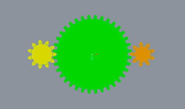
<1>Straight tooth cylindrical gear drive;
<2> Helical cylindrical gear drive
<3> herringbone gear transmission;
<4> bevel gear transmission;
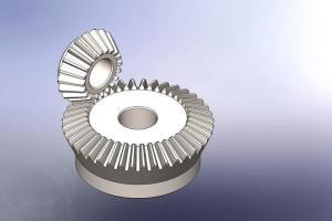
bevel gear
<5> cross-axis helical gear transmission.
According to the working conditions of the gear, it can be divided into:
<1>; Open gear transmission type gear transmission, the gears are exposed, and good lubrication cannot be guaranteed.
<2>; half-open gear transmission, the gear is immersed in the oil pool, with a protective cover, but not closed.
<3>; closed gear transmission, gears, shafts and bearings are all installed in a closed box, with good lubrication conditions, difficult for dust and sand to enter, accurate installation,
Gear transmission has good working conditions and is the most widely used gear transmission.
Gear transmission can be classified according to the relative position of its axis.
Gear drive can be divided into cylindrical gear drive, bevel gear drive, non-circular gear drive, rack drive and worm drive according to the shape of the gear.
According to the tooth profile curve, it can be divided into involute gear transmission, cycloid gear transmission and arc gear transmission. A transmission composed of more than two gears is called a gear train. The gear transmission can be divided into ordinary gear transmission and planetary gear transmission according to whether there are gears with axis movement in the gear train. The gears with axis movement in the gear train are called planetary gears. Gear transmission can be divided into closed type according to its working conditions
Gear transmission calculation
Open and semi-open transmission. Sealing the transmission in a rigid case and ensuring good lubrication is called closed transmission, which is more commonly used, especially for higher-speed gear transmissions, which must be closed transmission. Open transmission is exposed and cannot guarantee good lubrication. It is only used for low speed or unimportant transmission. Half-open transmission is somewhere in between.
The law of meshing: The smoothness of gear transmission requires the instantaneous transmission ratio in the process of gear tooth meshing i=angular speed of driving wheel/angular speed of driven wheel=ω1/ω2=constant, this requirement is guaranteed by tooth profile. Figure 2 shows that the two meshing tooth profiles E1 and E2 are in contact at any point K, and the common normal line N1N2 of the two tooth profiles is made through the point K, which intersects the connecting center line O1O2 at point C. The condition for maintaining contact during the meshing process of the two tooth profiles is that the velocity of the K point on the tooth profile E1, vK1, and the K point velocity on the tooth profile E2, vK2, are equal in the direction of the common normal line N1N2, that is, vKn1=vKn2=vKn. Make perpendicular lines from O1 and O2 to the N1N2 line and intersect at points N1 and N2. The above formula shows that the two-wheel tooth profile must meet the following conditions: “No matter where the two-wheel tooth profile is in contact at any position, the common normal line passing through the contact point must pass the fixed point C ─ ─ node on the connecting center line.” This is a circular gear. The basic law of tooth profile meshing. There are many curves that can meet this law. In fact, the requirements of manufacturing, installation and load-bearing capacity should be considered. Generally, only involute, cycloid and arc are used as the working tooth profile of the gear. Part of the tooth profile is involute.
For involute gears, the base radius rb1 and rb2 of wheel 1 and wheel 2 are respectively. The N1N2 line is the internal common tangent of the two base circles, that is, the common normal of any contact point of the two tooth profiles coincides with it. Because the two base circles have only one internal common tangent in one direction, the common normal of any contact point passes through the fixed point C, which shows that using an involute as the tooth profile conforms to the basic law of tooth profile meshing.
The two circles drawn through node C with O1 and O2 as the centers are called pitch circles. The pitch radius of wheel 1 and the pitch radius of wheel 2 Involute gears have the following characteristics: ①N1N2 is the trajectory of the contact points of the two tooth profiles, called the meshing line, which is a straight line. ②The common tangent line tt of the two pitch circles of gear transmission through node C is called the meshing angle α’between it and the meshing line N1N2, which is a constant. ③The pressure between the tooth surfaces is always along the direction of the common normal line N1N2 of the contact point, so the pressure direction between the tooth surfaces does not change when the involute gear transmits power. ④The transmission ratio is inversely proportional to the radius of the base circle of the two wheels. After the gear is made, the base circle is determined. Therefore, even if the center distance is slightly deviated from the design during operation, the transmission ratio will not be affected. This feature is called the separability of the transmission. It affects the processing, assembly and Maintenance is very beneficial. ⑤The two tooth profiles only have no sliding between the tooth surfaces when the node C is in contact, and there is sliding between the tooth surfaces when they are in contact at other points, and the farther away from the node, the greater the sliding. ⑥Since the involute gear can mesh with a rack with a linear tooth profile, it can be processed by a tool with a linear tooth profile. The tool is easy to manufacture and the machining accuracy can be high.
Coincidence degree: Coincidence degree is an important parameter that affects the continuous transmission of gears. As shown in Figure 2, gear tooth meshing starts from the contact between the tooth root of the driving wheel and the tooth tip of the driven wheel, that is, the intersection A of the tooth tip circle of the driven wheel and the meshing line is the starting point of meshing. As the wheel 1 rotates, the wheel 2 is pushed to rotate, and the contact point moves along the meshing line. When the contact point moves to the intersection E of the addendum circle of the wheel 1 and the meshing line (the dotted line in the figure), the tooth profile When the meshing ends, the two tooth profiles begin to separate. Point E is the meshing end point, which is the actual meshing line length. If the front pair of teeth are still in contact at point D before point E, and the latter pair of teeth are in contact at point A, then the transmission is continuous; if the front pair of teeth has left at point E, and the latter pair has not yet entered meshing , Then the transmission is interrupted. Considering the influence of gear manufacturing, installation errors and deformation, ε≥1.1~1.4 is often required in practice. The greater the coincidence degree, the more stable the transmission. The above refers to the coincidence degree of the end face of the cylindrical gear, and there is a longitudinal coincidence degree for the helical cylindrical gear.
The condition for a pair of gears to be able to mesh correctly is that they must have equal modulus and equal pressure angle.
TH Valve is a professional manufacturer of butterfly valve, gate valve, check valve, globe valve, knife gate valve, ball valve with API, JIS, DIN standard, used in Oil, Gas, Marine industry, Water supply and drainage, fire fighting, shipbuilding, water treatment and other systems, with Nominal Diameter of DN50 to DN1200, NBR/EPDM/VITON, Certificates & Approvals: DNV-GL, Lloyds, DNV, BV, API, ABS, CCS. Standards: EN 593, API609, API6D
Related news /knowledge:
what is Spur gear?
Types of mechanical transmission;
Common failures of butterfly valves and the characteristics of installation
Stainless steel valve material parameters and specific applications