Electric globe valve selection and application
Electric shut-off valve selection, Electric shut-off valve application, globe valve also named shut off valve or cut off valve.
Advantages of electric shut-off valve:
Once the electric shut-off valve is in the open state, there is no contact between its valve seat and the sealing surface of the disc, so its sealing surface is less mechanically worn, because most of the electric shut-off valves have relatively easy repairs. Or there is no need to remove the entire valve from the pipeline when replacing the sealing
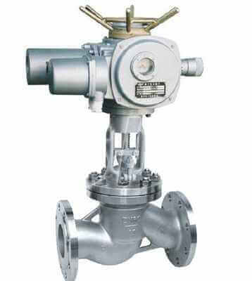
electric globe valve
element,which is very suitable for the occasion where the valve and the pipeline are welded together. The most obvious advantage is that during the opening and closing process, the friction between the disc and the sealing surface of the valve body is smaller than that of the gate valve, so it is wear-resistant. The opening height is generally only 1/4 of the diameter of the valve seat passage, so it is much smaller than the gate valve. Usually there is only one sealing surface on the valve body and the valve flap, so the manufacturing process is better and it is easy to maintain. The flow direction of the medium through this type of valve has changed, so the flow resistance of the electric shut-off valve is higher than that of other valves.
Selection of electric shut-off valve:
Commonly used electric globe valves are electric straight-through globe valves, electric throttle valves, electric angle globe valves, electric DC globe valves, electric plunger globe valves, etc. In addition to electric throttle valves, other electric globe valves generally do not Make high-pressure choices.
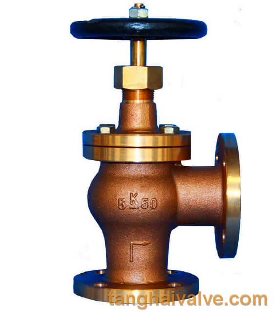
1. Angle type electric shut-off valve; in the angle type electric shut-off valve, the fluid only needs to change its direction once, so that the pressure drop through this valve is smaller than that of the conventional structure of the electric shut-off valve.
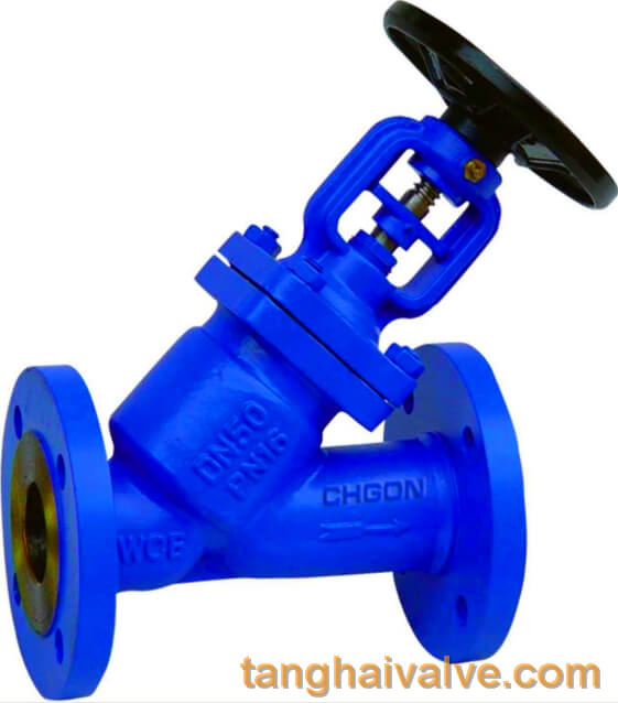
2. DC type electric shut-off valve; electric shut-off valve in the DC type or Y-shaped electric shut-off valve, the flow passage of the valve body is in a diagonal line with the main flow path, so that the degree of damage to the flow state is smaller than that of the conventional electric shut-off valve, so it passes The pressure loss of the valve is correspondingly small.
3. Plunger type electric shut-off valve: This type of electric shut-off valve is a modification of the conventional electric shut-off valve. In this valve, the disc and valve seat are usually designed based on the plunger principle. The valve clack is polished so that the plunger and the valve stem are connected, and the sealing is achieved by two elastic sealing rings sleeved on the plunger. The two elastic sealing rings are separated by a sleeve ring, and the sealing ring around the plunger is pressed firmly by the load exerted on the bonnet by the bonnet nut.
Electric shut-off valve application:
If the electric shut-off valve is used in high-pressure occasions, it is generally connected by butt welding, or electric angle type shut-off valve is used. According to the material, you can choose carbon steel or 304 stainless steel. If the temperature is relatively high, you need to choose chromium-molybdenum steel or chromium-molybdenum-vanadium steel. The typical J941Y-170V electric high temperature and high pressure stop valve used in power plants.
TH Valve is a professional manufacturer of butterfly valve, gate valve, check valve, globe valve, knife gate valve, ball valve with API, JIS, DIN standard, used in Oil, Gas, Marine industry, Water supply and drainage, fire fighting, shipbuilding, water treatment and other systems, with Nominal Diameter of DN50 to DN1200, NBR/EPDM/VITON, Certificates & Approvals: DNV-GL, Lloyds, DNV, BV, API, ABS, CCS. Standards: EN 593, API609, API6D
Related news /knowledge:
Classification of the globe valves-(1);
The working principle and characteristics of the globe valve;
Electric globe valve model coding method.
working principle of electric globe valve;